Creating a Smart LED Dimmer
April 28, 2022Table of Contents
Introduction
I frequently see cheap battery-operated monochrome string lights on clearance at stores locally such as Walmart. I wanted to be able to take advantage of these deals, but most of the lighting equipment that I own is "smart" and tied into the Home Assistant home automation system. I wanted to be able to bring these lights into my home automation system to control them more easily and tie them into my automations. There is the QuinLED controller, but it was a little overkill for these types of cheap monochrome string lights.
Solution Proposal
I was looking for a device to satisfy the following requirements:
- The device should be able to control at least one set of string lights (bonus points for multiple sets).
- The device should be able to control the brightness of the lights.
- The device should be able to control them via Home Assistant.
- Bonus points for extra headers for peripheral devices such as a PIR Motion Sensor.
- Bonus points for an onboard temperature sensor. They're cheap and can serve a variety of purposes for automations.
I created the following solution.
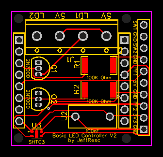
Schematic

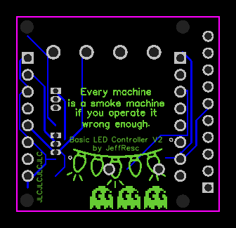
PCB Layout


Parts List
These are the parts I decided to go with for my build. It was purely based on availability and cost. I was not familiar with many of these brands (other than Sensirion) before using them, but I have not had any issues with my device.
| Name | Designator | Footprint | Quantity | Manufacturer Part | Manufacturer | Supplier | Supplier Part |
|---|---|---|---|---|---|---|---|
| Header-Male-2.54_1x10 | H1 | HDR-TH_10P-P2.54-V-M-1 | 1 | Headers Pins2.54mm1*10P | LCSC | C57369 | |
| ESP32 Left | P1 | HDR-TH_8P-P2.54-V-F-1 | 1 | Female headerHDR1X8-2.54 | BOOMELE | LCSC | C27438 |
| ESP32 Right | P2 | HDR-TH_8P-P2.54-V-F-1 | 1 | Female headerHDR1X8-2.54 | BOOMELE | LCSC | C27438 |
| 2N7000 | Q1,Q2 | TO-92-3_L4.9-W3.7-P1.27-L | 2 | 2N7000 | CJ | LCSC | C9114 |
| 100K | R1,R2 | R2512 | 2 | RMC2512100K1%N | Tyohm | LCSC | C269364 |
| Screw Terminal Block | U1 | CONN-TH_JL301-50004U01 | 1 | JL301-50004U01 | JILN(锦凌) | LCSC | C1509680 |
| 100nF | U2 | CAP-TH_L10.5-W5.0-P7.50-D1.2 | 1 | - | Tongfeng | LCSC | C281835 |
| SHTC3 | U3 | SENSORM-SMD_4P-L2.0-W2.0-P1.00 | 1 | SHTC3 | Sensirion | LCSC | C194656 |
Other than that, you will also need a WeMos D1 MINI ESP32 or WeMos D1 ESP8266. The device is designed to work with either, but I have found it to work best with the ESP32 as it is more powerful and the ESP32 LEDC Output is a much better solution than the ESP8266 Software PWM Output.
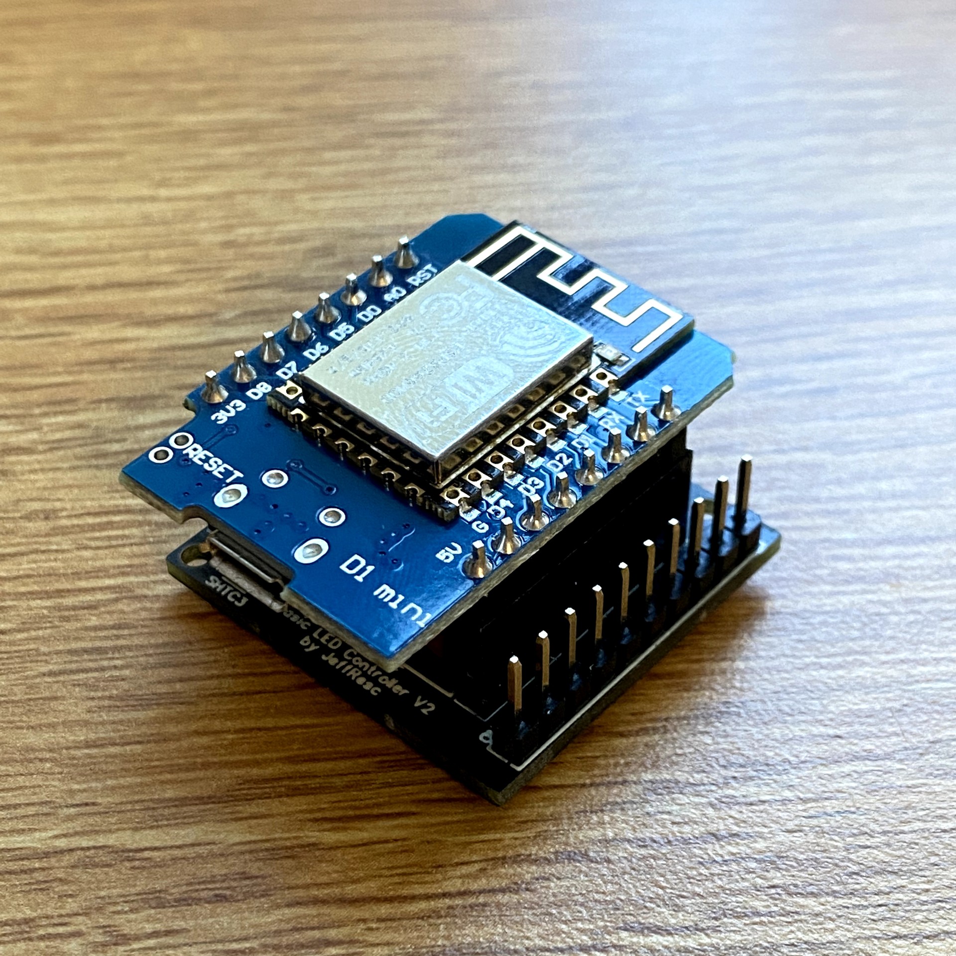
Digital Render
This is a digital render of the board using MeshLab.

Software
For the software to control the onboard ESP32 (or ESP8266), I decided to go with ESPHome due to its ease of use, especially with Home Assistant. This is an example that I wrote which treats both LED outputs as one controller, that way two sets of lights can be controlled simultaneously. It can also read the value of the onboard SHTC3 and report back to Home Assistant.
substitutions:
  devicename: bld-v2-01
  friendly_name: Hallway Mirror Lights

esphome:
  name: ${devicename}
  platform: ESP32
  board: wemos_d1_mini32

wifi:
  ssid: !secret wifi_ssid
  password: !secret wifi_password
  fast_connect: true
  ap:
    ssid: ESP-${devicename}
    password: !secret fallback_password

captive_portal:

web_server:
  port: 80
  auth:
    username: !secret web_username
    password: !secret web_password

api:
  password: !secret api_password

ota:
  password: !secret ota_password
  safe_mode: True

i2c:
  sda: GPIO21
  scl: GPIO22
  scan: true
  id: bus_a

sensor:
  - platform: shtcx
    temperature:
      name: ${friendly_name} Temperature
      filters:
      - lambda: return x * (9.0/5.0) + 32.0;
      unit_of_measurement: "°F"
    humidity:
      name: ${friendly_name} Humidity
    update_interval: 60s

light:
  - platform: monochromatic
    name: ${friendly_name}
    output: LD1_LD2
    id: main_light
    gamma_correct: false
    restore_mode: RESTORE_DEFAULT_OFF

output:
  - platform: template
    id: LD1_LD2
    type: float
    write_action:
      - output.set_level:
          id: LD1
          level: !lambda return state;
      - output.set_level:
          id: LD2
          level: !lambda return state;
  - platform: ledc
    id: LD1
    pin: GPIO26
    # You may want to configure a maximum power output depending on your particular lights, to ensure they are not damaged by being over-powered.
    # max_power: 0.60
    frequency: 1220Hz
  - platform: ledc
    id: LD2
    pin: GPIO23
    # You may want to configure a maximum power output depending on your particular lights, to ensure they are not damaged by being over-powered.
    # max_power: 0.60
    frequency: 1220Hz
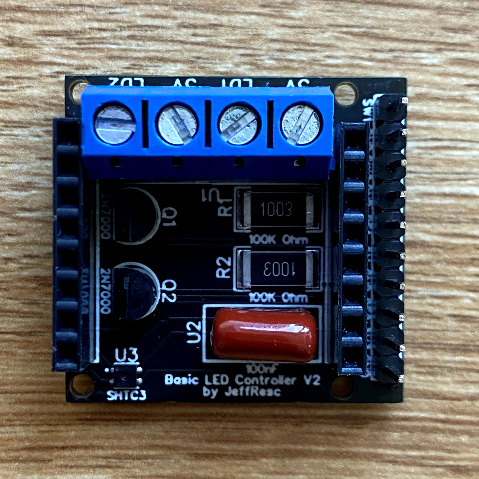
Final Results
I sent the final design files to JLCPCB for production. They are by far the cheapest PCB manufacturer to my knowledge, and I am satisfied with the build quality for these types of projects.

